

Wi-Fi 5 vs Wi-Fi 6 vs Wi-Fi 7 for Mini PCs: The 2026 Industrial Buying Guide
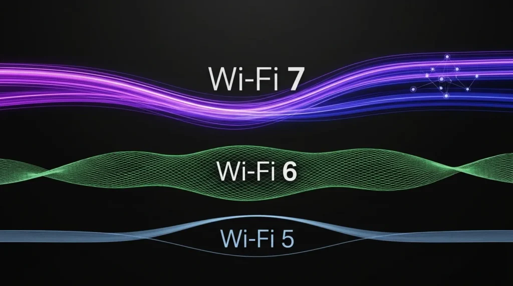
Wi-Fi 5 vs Wi-Fi 6 vs Wi-Fi 7 for Mini PCs: The 2026 Industrial Buying Guide Announcements Buyer Guide Comprehensive Tips Occasion Product Review Q&A Tutorials Real speed depends on your wireless module. Here is how to choose the right Wi-Fi for a standard or industrial mini PC in 2026. TL;DR — for busy buyers Wi-Fi 6 is the safe default for most mini PCs in 2026. Wi-Fi 7 shines for high throughput, AGV mobility, and future-proof industrial builds. Wi-Fi 5 still works below 500 Mbps with light, single-device use. Match your router first. The router sets the real speed ceiling. On AMD mini PCs, choose MediaTek MT7925 or a Qualcomm Wi-Fi 7 module. Avoid Intel BE200. Most mini PCs take M.2 2230 E-key modules, so you can upgrade later. Why Your Wi-Fi Choice Matters Compared to traditional desktop computers, the HYSTOU Business Mini PC occupies significantly less space. Whether placed in a remote home office or a studio, it solves space resource shortages, allowing for a more efficient arrangement of office supplies. Furthermore, its compact size enables easy portability, letting small businesses with remote teams flexibly arrange workspaces and empowering employees to work from various locations. Wi-Fi Generations at a Glance Wi-Fi names follow generations, not versions. Each generation adds new features. Each one also raises certified speeds. The table below maps the key facts. Generation Standard (year) Bands Max channel Theoretical peak Key features Wi-Fi 5 802.11ac (2014) 5 GHz 160 MHz ~3.5 Gbps 256-QAM; MU-MIMO Wi-Fi 6 802.11ax (2019) 2.4 + 5 GHz 160 MHz 9.6 Gbps OFDMA; 1024-QAM; TWT Wi-Fi 6E 802.11ax (2021) adds 6 GHz 160 MHz 9.6 Gbps 6 GHz band; Wi-Fi 6 features Wi-Fi 7 802.11be (2024) 2.4 + 5 + 6 GHz 320 MHz ~46 Gbps (8-stream lab max; a common 2×2 mini PC module peaks around 5.8 Gbps at 320 MHz) MLO; 4K-QAM; low latency Theoretical peaks come from lab conditions. Real throughput depends on your router, distance, and interference. Treat the table as a guide, not a promise. Three Facts That Decide Your Real Speed Spec sheets list limits. Real life follows three rules. Keep them in mind before you compare numbers. Your router sets the ceiling A Wi-Fi 7 card cannot outrun a Wi-Fi 5 router. The link negotiates down to the lower generation. In practice, upgrade the router first if it is old. Then a newer Wi-Fi module makes sense. Your broadband plan sets the need A 500 Mbps plan runs fine on Wi-Fi 5. A 1 Gbps plan is comfortable on Wi-Fi 6. Plans above 2 Gbps start to justify Wi-Fi 7. That said, local transfers matter too. Moving files between a NAS and a mini PC can use far more than your internet speed. Spectrum rules vary by country The 6 GHz band is open in the United States and in parts of Europe. Some regions still restrict it. Meanwhile, Wi-Fi 7 still improves on 5 GHz through MLO. Always check local regulation before you plan around 6 GHz. How to Choose Wi-Fi for a Standard Mini PC Most mini PCs serve typical home or office roles. The best choice follows the workload. Use the scenarios below as a starting point. Home office and streaming. Wi-Fi 5 handles this well below 500 Mbps. Wi-Fi 6 adds headroom for multiple tabs and devices. For example, a family with shared video calls will feel the difference. Multi-device households. Wi-Fi 6 wins here. OFDMA serves many devices at once. Older generations queue traffic instead. Gaming and VR. Latency matters more than peak speed. Wi-Fi 6E or Wi-Fi 7 keeps input lag low. Wi-Fi 5 may feel sluggish in crowded homes. NAS and local media servers. Local transfers need real bandwidth. Wi-Fi 6E or Wi-Fi 7 handles large files well. Wi-Fi 5 often becomes the bottleneck. In short, choose Wi-Fi 6 for most buyers. Choose Wi-Fi 6E or Wi-Fi 7 when local throughput, latency, or future-proofing matters. The price gap keeps shrinking. Choosing Wi-Fi for Industrial Mini PCs Industrial mini PCs work differently. They run around the clock. They face heat, vibration, dust, and crowded radio environments. Reliability matters more than peak speed. As a result, the decision criteria change. This also holds for an industrial mini PC for AGV fleets, where a dropped link can stop a moving robot. Three principles come first. Wire fixed machines where possible. Wireless should serve mobility and hard-to-reach spots. Plan bands deliberately. Use 2.4 GHz for range, 5 GHz and 6 GHz for throughput. Remember that 2.4 GHz is crowded. Bluetooth, microwaves, and Zigbee all share it. Beyond that, secure and manage the network. WPA3-Enterprise plus a single SSID across access points keeps roaming smooth. Industrial scenario Recommended Wi-Fi and why Factory automation (HMI/PLC) Wi-Fi 6 with a wired backup. Steady low-latency links, and OFDMA suits many devices on one floor. Machine vision and inspection Wi-Fi 6E/7 or wired 2.5G. Camera streams need high bandwidth with low jitter. AGV / AMR robots Wi-Fi 7 with Multi-Link Operation (MLO), or Wi-Fi 6 with fast roaming. MLO sends data on 5 GHz and 6 GHz at once. If one band hits interference, the other keeps the link alive. Digital signage and POS Wi-Fi 6. Wide coverage plus easy remote management across sites. Edge AI and local LLM Wi-Fi 7 or wired 2.5G. Model and dataset sync demand real throughput. A fanless mini PC with Wi-Fi 7 fits this role well in dusty plants. Outdoor and harsh sites Wi-Fi 6 with external antennas. Range and durability beat peak speed here. Why MLO matters for moving machines Why MLO matters for moving machines Can You Upgrade the Wi-Fi Module Later? Most mini PCs ship with a removable module. The common form factor is M.2 2230 with an E-key. That opens a clear upgrade path. Still, the choice is not purely mechanical. Platform compatibility matters just as much as the slot. Here is the compatibility map for popular modules. It links each card to its interface and to the CPU
Wi-Fi 5 vs Wi-Fi 6 vs Wi-Fi 7 for Mini PCs: The 2026 Industrial Buying Guide Read More »