The Ultimate Mini PC BIOS Tuning Guide: Power Walls, PL1/PL2, PBO & Thermal Management
Mini PCs deliver impressive desktop-grade performance in an incredibly compact form factor. However, their small physical chassis creates strict limitations on heat dissipation and power delivery. By default, motherboard manufacturers set highly conservative power limits to prioritize safety and low acoustics, often leaving significant hardware potential on the table.
Tuning your CPU’s core power parameters directly in the BIOS is the most effective way to customize your computing experience. This guide breaks down the underlying physics of hardware “power walls,” provides a universal framework for adjusting these limits across both Intel and AMD platforms, and shares field-tested presets to optimize your device for silence, balance, or raw speed.
The Physics of Power Walls: Dual-Platform Parameters Explained
Before altering any hardware settings, you must understand the energy management metrics governing modern mobile and ultra-small form factor (USFF) processors.
Intel Power Architecture (PL1, PL2, Tau)
Intel platforms manage power through a time-decay window system designed to maximize short-term responsiveness while protecting long-term thermal limits.
- PL1 (Sustained Power Limit): The long-term power envelope (measured in Watts) the CPU can maintain under continuous, steady-state multi-threaded workloads (e.g., 3D rendering, video exporting). It is typically mapped closely to the processor’s nominal TDP (Thermal Design Power).
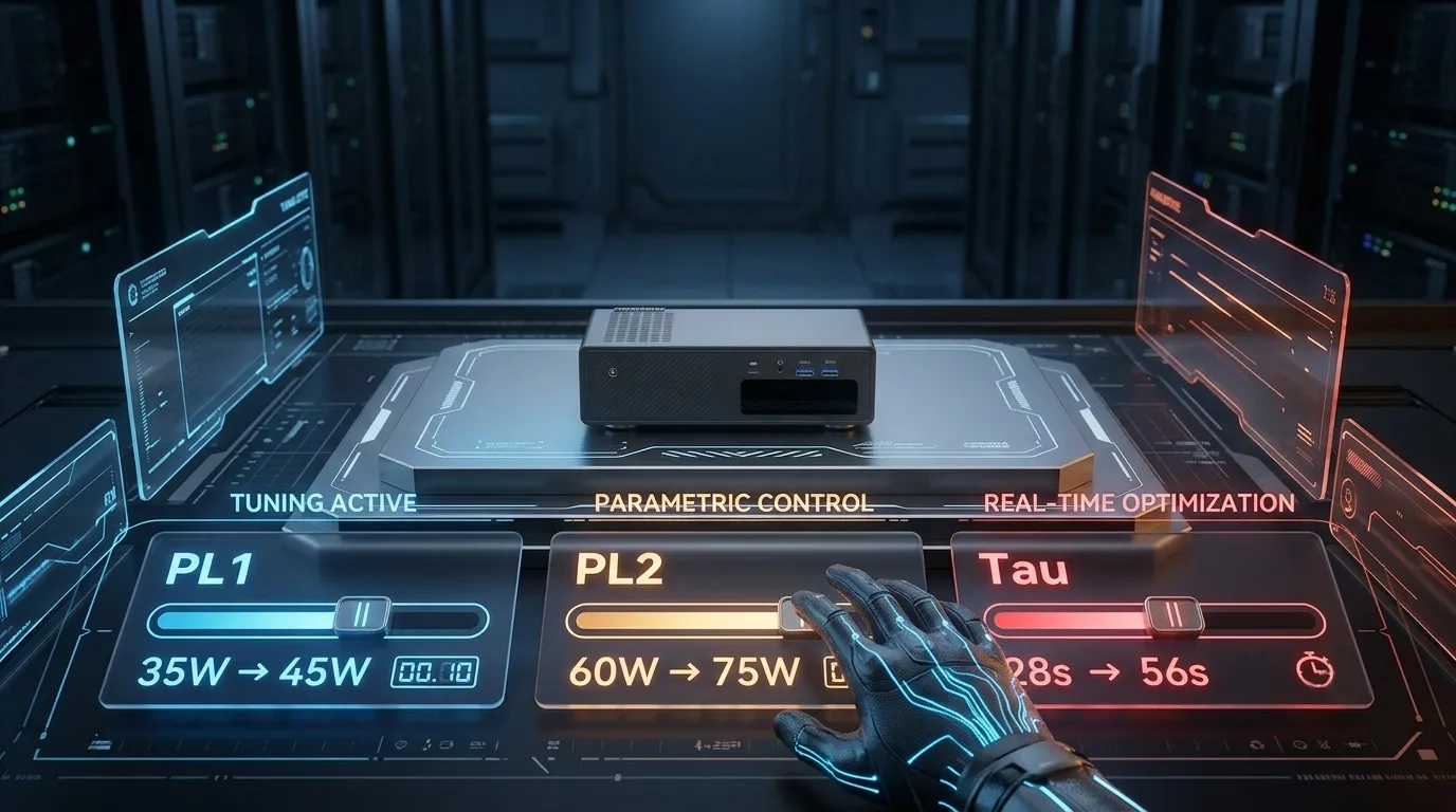
- PL2 (Burst Power Limit): The short-term maximum power ceiling allowed during brief workload spikes (e.g., loading a heavy webpage, launching an application). PL2 is usually 1.5x to 2x higher than PL1.
- Tau (Turbo Time Limit): A dedicated timing constant (in seconds) that dictates exactly how long the processor is allowed to draw power up to the PL2 ceiling before safely decaying back down to the sustained PL1 envelope.
AMD Power Architecture (PPT, TDC, EDC)
AMD’s Precision Boost Overdrive (PBO) framework achieves the same thermal-electrical balance as Intel but breaks its safety metrics down into three distinct hardware boundaries:
- PPT (Package Power Tracking): The absolute total power delivery threshold (in Watts) allowed across the entire processor socket. This is the direct functional equivalent to Intel’s PL1/PL2 mechanics.
- TDC (Thermal Design Current): The maximum sustained electrical current (in Amperes) that the motherboard’s VRMs (Voltage Regulator Modules) can supply when thermally limited (under continuous heavy loading).
- EDC (Electrical Design Current): The absolute peak, short-term electrical current (in Amperes) the motherboard VRM can supply during instantaneous burst spikes.
Universal Workflow: Accessing and Locating Limits
While exact BIOS menu layouts vary wildly between motherboard vendors (AMI, Insyde, Phoenix), the underlying structural logic remains highly consistent across almost all x86 Mini PCs.
Entering the Motherboard Firmware
Cold Boot: Completely shut down your system. Do not use Sleep or Hibernate profiles.
The Post Window: Press the physical power button, then immediately and repeatedly press the system’s designated BIOS hotkey before the operating system begins loading.
- Common Mini PC Hotkeys: Delete (Del) or F2 enter the setup utility on 90% of USFF devices. F11 or F7 typically opens the temporary, one-time boot menu.
Advanced Mode: If your device boots into a simplified “EZ-Mode” dashboard, look for an “Advanced Mode” toggle (usually mapped to F6 or F7) to unlock core hardware granular controls.
Navigation Paths for Both Architectures
Once inside Advanced Mode, use your keyboard arrow keys to locate the power registers based on your chip’s architecture:
For Intel Systems
Typical Paths:
Advanced > CPU Configuration > CPU Power Management > Turbo Power LimitsORChipset > Advanced Host Controller > Power & PerformanceAction: Locate Long Duration Power Limit (PL1) and Short Duration Power Limit (PL2). Switch their configurations from Auto to Manual / Enabled to open the numerical entry fields.
For AMD Systems
Typical Paths:
Advanced > AMD CBS > SMU Common OptionsORAdvanced > AMD Overclocking > Precision Boost OverdriveAction: Change the Precision Boost Overdrive selection from Auto to Advanced. This will reveal editable numeric fields for PPT Limit (mW), TDC Limit (mA), and EDC Limit (mA).
Crucial Safety Note: AMD BIOS structures frequently calculate these fields in milliwatts (mW) and milliamperes (mA). To set a PPT of 45W, you must input
45000.
Scenario-Based Tuning Presets (Universal Calibration Table)
Because different processors feature vastly different baseline power envelopes, tuning cannot follow a “one-size-fits-all” number. Use this calibrated taxonomy matrix based on your device’s form factor and thermal capabilities.
| Tuning Profile | Intel Configuration (PL1 / PL2 / Tau) | AMD Configuration (PPT / TDC / EDC) | Target Use Cases & Acoustic Goals |
Silent Profile | PL1: 25W–30W | PPT: 25W (25000mW) | Home Theater PCs (HTPC), 4K media servers, quiet nighttime office work. Capping limits prevent fan revving. |
Balanced Profile | PL1: 45W–50W | PPT: 45W–50W | Daily multitasking, software engineering, light video editing, casual gaming. Optimized performance per watt. |
Performance Profile | PL1: 55W–65W | PPT: 55W–65W | Sustained heavy compiles, 3D rendering, video exports, high-framerate gaming. Requires aggressive custom fan profiles. |
Stability Validation & Throttling Diagnostics
Forcing higher wattages through a compact motherboard yields zero performance gains if the system instantly encounters a hardware bottleneck. You must scientifically validate your configuration changes.
The Scientific Verification Loop
Launch HWiNFO64 (Windows) or Mangohud/Sensors (Linux) before initiating workloads. Configure the software to display real-time CPU Package Power, Core Temperatures, and effective clock multipliers.
Execute a quick Cinebench loop. Monitor your software to confirm the CPU successfully reaches your custom short-term burst values (PL2/PPT) and remains there for the exact duration of your configured Tau window.
Subject the device to a sustained stress vector using AIDA64 (Stress FPU) or Prime95 (Small FFTs). If the operating systemblue-screenss, freezes, or hard-reboots, your cooling or power delivery can’t sustain the profile. Drop values by 3W and retest.
Decoding Throttling Flags
When a Mini PC encounters an insurmountable hardware ceiling, it preserves its silicon by dropping clock speeds. HWiNFO64 tracks these states under the “Performance Limit Reasons” menu. Use this breakdown to diagnose your limits:
Thermal Throttling (PROCHOT): The core temperature hit the maximum safe silicon threshold (typically 95°C–100°C).
Remedy: Clean internal dust filters, optimize the physical airflow surrounding the chassis, lower your PL1/PPT value, or adjust the BIOS fan curve to hit 100% speed earlier (e.g., at 80°C).
Power Limit Throttling (PL1/PL2/PPT): The processor capped its clock scaling because it hit the exact numeric wattage wall you input in the BIOS.
Interpretation: This is intentional and correct behavior—it proves the custom limits are successfully enforcing your performance-heat ceiling.
VRM / Current Throttling (ICC Max/TDC/EDC): The power draw reached the maximum electrical amperage capacity of the motherboard’s voltage regulator delivery system.
Interpretation: You have officially reached the absolute structural hardware ceiling of the physical circuit board. Raising power limits further will provide zero performance gains.
Frequently Asked Questions
Can I raise PL2 higher than the rated wattage of my external power brick?
Absolutely not. Your Mini PC’s total power draw includes the CPU (PL1/PL2), RAM, SSD, Wi-Fi module, and USB peripherals. If your external power brick is rated for 90W, setting your CPU PL2 to 80W will likely cause the system to abruptly black-screen, reboot, or trigger the power supply’s Over-Current Protection (OCP) under heavy burst loads. Always leave at least a 20W–30W buffer for the rest of the system.
Why does my Cinebench score decrease after I raised the PL1/PL2 limits?
This is a classic symptom of Thermal Throttling occurring too early. When you raise PL2 significantly without an aggressive fan curve or premium cooling, the CPU spikes in heat so rapidly that it instantly hits its thermal ceiling (95°C+). The system then forcefully drops clock speeds lower than stock values to cool down. In small form factor PCs, lower power limits with better thermal consistency often yield higher performance than unstable high limits.
What should I do if my Mini PC refuses to turn on (fails to POST) after an adjustment?
If an aggressive configuration causes the system to hang at a black screen upon booting, you must manually reset the system firmware variables to factory defaults. Power off the device completely, remove the physical DC power cable from the back, open the bottom structural panel of the chassis, and either remove the circular silver CMOS battery for 5 minutes or short the designated CLR_CMOS Jumper pins on the motherboard using a metal screwdriver tip for 10 seconds.
Why does my performance drop even though temperatures are below 75°C?
This scenario points directly to either an intentional Power Limit Throttling state or VRM thermal saturation. If the CPU cores themselves are running quite cool, but the small, unheatsinked VRM chips sitting next to the socket are overheating, the motherboard will force down the CPU’s clock speeds to prevent power delivery component failure.

Author: Nick FU
Marketing Specialist | HYSTOU Mini PC & Network Appliance Manufacturer
HYSTOU has established its R&D headquarters in Shenzhen, drawing on over a decade of experience. Our core team members, who previously served at renowned companies such as Inventec and Quanta Computer, form the backbone of our technical expertise. With robust R&D and innovation capabilities, we remain steadfast in our commitment to pursuing excellence in the field of technology products.